Page Contents:
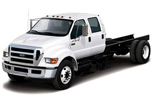
In this article, you will find information about the fuses of the Ford F-650 / F-750 (models 2011, 2012, 2013, and 2015), including diagrams of the fuse boxes, a list of fuses and relays, their designation, and the location of the fuse blocks within the vehicle.
Checking and Replacing Fuses in Ford F-650 / F-750
If electrical components in the vehicle are not working, a fuse may have blown. Blown fuses are identified by a broken wire within the fuse. Check the appropriate fuses before replacing any electrical components. To remove a fuse use the fuse puller tool provided on the fuse panel cover.
Caution!
- Always replace a fuse with one that has the specified amperage rating. Using a fuse with a higher amperage rating can cause severe wire damage and could start a fire.
- Always disconnect the battery before servicing high current fuses.
- Always replace the cover to the power distribution box before reconnecting the battery or refilling fluid reservoirs.
Location of Fuse Boxes
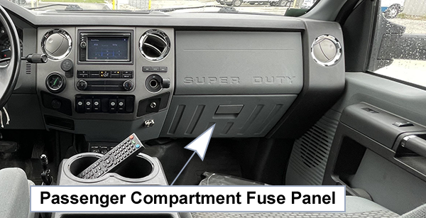
Passenger Compartment Fuse Panel:
The fuse box is located behind the passenger airbag cover and can be accessed through the glove box.
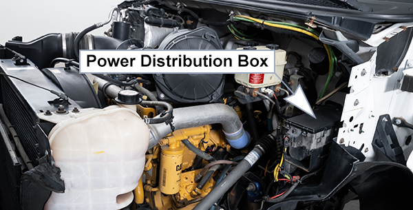
Power Distribution Box:
The power distribution box is located in the engine compartment. The power distribution box contains high-current fuses that protect your vehicle’s main electrical systems from overloads.
Fuse Box Diagrams
2011
Passenger Compartment Fuse Panel
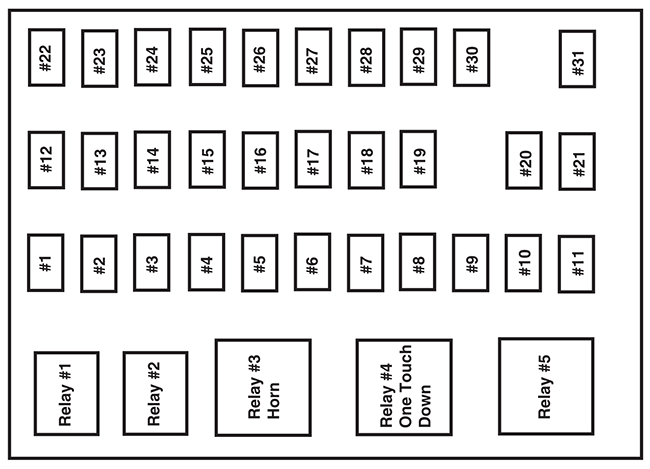
| № | A | Fuse description |
|---|---|---|
| 1 | 20A | Horn |
| 2 | 15A | Flasher relay |
| 3 | 20A | Power point |
| 4 | 10A | Data Link Connector (DLC), Engine diagnostic connector, Parking brake warning |
| 5 | 15A | Run relay |
| 6 | - | Not used |
| 7 | - | Not used |
| 8 | 5A | Radio, GEM |
| 9 | 5A | Power window relay |
| 10 | 15A | Heated mirrors |
| 11 | 5A | Wiper and washer systems |
| 12 | 10A | Transmission shift selector |
| 13 | 20A | Radio, Power mirrors |
| 14 | 10A | Interior lamp relay |
| 15 | 10A | Interior lamp relay |
| 16 | 15A | High beams, Indicator |
| 17 | - | Not used |
| 18 | 5A | Dimmer switch, Interior lighting |
| 19 | 15A | Engine control |
| 20 | 5A | Starting system |
| 21 | 10A | DRL resistor |
| 22 | 15A | Air horn, Air suspension dump, Two-speed axle, Driver-controlled locking differential |
| 23 | 10A | Flasher relay |
| 24 | 15A | ABS relay, Fuel heater relay, Air dryer |
| 25 | 10A | Blower motor relay |
| 26 | 10A | Right-hand low beam headlight |
| 27 | - | Not used |
| 28 | 10A | Left-hand low beam headlight |
| 29 | 10A | Cluster, GEM |
| 30 | 15A | Allison electronic transmission |
| 31 | 15A | Mirror fold relay |
| Relay 1 | - | Interior lamps |
| Relay 2 | - | Not used |
| Relay 3 | - | Horn |
| Relay 4 | - | Not used |
| Relay 5 | - | Not used |
Power Distribution Box
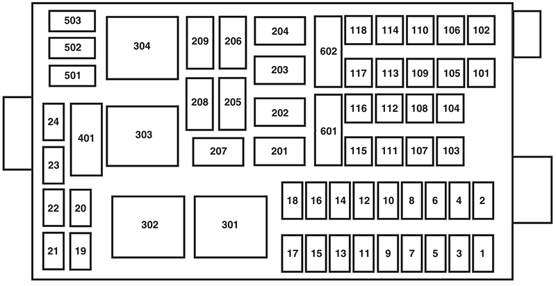
| № | A | Fuse description |
|---|---|---|
| 1 | 20A | Upfitter switches (AUX 2 and AUX 4) |
| 2 | 30A | Power seat (driver) |
| 3 | 30A | Power seat (passenger) |
| 4 | 15A | Windshield washer relay, Washer pump motor |
| 5 | 5A | Brake warning switch (hydraulic brake only) |
| 6 | 20A | Upfitter switches (AUX 1 and AUX 3) |
| 7 | 15A | Brake pressure switches, ABS event relay |
| 8 | 20A | DEF (Urea), Line heaters |
| 9 | 20A | Ignition switch, Starter cutoff |
| 10 | 15A | Air tank moisture removal valve |
| 11 | 30A | Electric trailer brake |
| 12 | 20A | Passenger compartment fuse box 5 and 21 |
| 13 | 15A | Instrument cluster/Gateway module |
| 14 | 20A | Nitrogen oxide sensor |
| 15 | - | Not used |
| 16 | 5A | Bendix Air ABS |
| 17 | - | Not used |
| 18 | 10A | Fuel transfer pump |
| 19 | - | Not used |
| 20 | - | Not used |
| 21 | - | Not used |
| 22 | - | Not used |
| 23 | - | Not used |
| 24 | - | Not used |
| 101 | 30A | Bendix Air ABS relay (Air brake vehicles only) |
| Hydraulic brakes module (Hydraulic brake vehicles only) | ||
| 102 | 20A | Ignition switch |
| 103 | 20A | Ignition switch, Passenger compartment fuse box fuses 19, 29 and 30 |
| 104 | 20A | Power point |
| 105 | 20A | Power door lock switches |
| 106 | 30A | Main light switch, Multi-function switch |
| 107 | 50A | Passenger compartment fuse box fuses 1,2, 3, 4, 12, 13, 14 and 15 |
| 108 | 40A | Fuel heater |
| 109 | 40A | Power window |
| 110 | 30A | Windshield wiper |
| 111 | 30A | Body builder relay, Parking lamps |
| 112 | 40A | Blower motor |
| 113 | 30A | Heated seats, Air-Ride seat |
| 114 | 20A | Aftertreatment DCU |
| 115 | 20A | Ignition switch, Passenger compartment fuse box fuses 8, 9, 10 and 11 |
| 116 | 30A | Left/Right turn relays, Back-up lamp relay |
| 117 | 20A | Stoplamps |
| 118 | 60A | Hydraulic brake vehicles (Trailer tow package only) |
| 601 | 60A | Trailer socket |
| 602 | 60A | Air brake trailer tow fuse block |
| 30A | Hydraulic brakes pump motor 2 | |
| 201 | - | Windshield washer relay |
| 202 | - | Wiper high/low relay |
| 203 | - | Wiper run/park relay |
| 204 | - | Windshield wiper relay |
| 205 | - | Body builder relay, right turn |
| 206 | - | Body builder relay, left turn |
| 207 | - | ABS event relay (Hydraulic brake vehicles only) |
| 208 | - | Body builder relay, back-up lamps relay |
| 209 | - | Auxiliary stoplamp relay |
| 301 | - | Fuel heater/Fuel transfer pump relay |
| 302 | - | Body builder relay, parking lamps relay |
| 303 | - | Blower motor relay |
| 304 | - | DEF (Urea) line heaters relay |
| 9925 | 30A | Hydraulic brakes pump motor 1 |
Relay Center
The relay center is located along the passenger side A-pillar on the right side of the footwell.

| № | Description |
|---|---|
| R1 | Spring applied hydraulic release warning chime module |
| R2 | A/C compressor clutch |
| R3 | Power Windows |
| R4 | Flasher (standard/LED) |
| R5 | Upfitter relay 1 |
| R6 | Upfitter relay 2 |
| R7 | Headlights |
| R8 | Spare |
| R9 | Upfitter relay 3 |
| R10 | Starter |
| R11 | DCU |
| R12 | Two-speed axle/Differential lock |
| R13 | Door lock |
| R14 | Air tank moisture valve |
| R15 | DRL #1 |
| R16 | Heated mirrors |
| R17 | Spare |
| R18 | Upfitter relay 4 |
| R19 | PRNDL display |
| R20 | Selective Catalyst Reduction (SCR) system (NOx) |
| R21 | Run |
| R22 | Door unlock |
| R23 | ABS warning indicator |
| R24 | DRL #2 |
| R25 | Park lights |
| R26 | Spare |
Trailer Tow Relays (If Equipped)

| № | A | Description |
|---|---|---|
| 1 | 30A* | Trailer tow ABS feed (non electric trailer brake vehicles only) |
| 2 | 30A* | Trailer tow park/marker lamps |
| 3 | 30A* | Trailer tow stop lamps |
| 4 | 30A* | Trailer tow turn/stop lamps (combined) |
| Trailer tow turn lamps (separate) | ||
| 5 | - | Not used |
| R1 | - | Trailer tow ABS relay (non electric trailer brake vehicles only) |
| R2 | - | Trailer tow marker lamp relay |
| R3 | - | Trailer tow stop lamp relay |
| R4 | - | Trailer tow tail lamp relay |
| R5 | - | Not used |
| R6 | - | Not used |
| R7 | - | Trailer tow left turn lamp relay |
| R8 | - | Trailer tow right turn lamp relay |
| *Maxi fiise | ||
Inline fuses
Your vehicle may have several inline fuses located in/on the battery cables located in the battery box depending on application.
- All Allison transmission equipped vehicles have a 10 Amp fuse located in the clean power cables located in the battery box.
- All vehicles have a 30 Amp fused located in the clean power cables located in the battery box.
- All vehicles equipped with an Eaton transmission have a 30 Amp fuse located in the clean power cables located in the battery box.
- All Hydraulic brake equipped vehicles have a 40 Amp fuse located in the clean power cables located in the battery box and in addition another 30 Amp fuse located in a fuse holder just above the power distribution center located in the vehicles engine compartment.
2012
Passenger Compartment Fuse Panel

| № | A | Description |
|---|---|---|
| 1 | 20A | Horn |
| 2 | 15A | Flasher relay |
| 3 | 20A | Power point |
| 4 | 10A | Data Link Connector (DLC), Engine diagnostic connector, Parking brake warning |
| 5 | 15A | Run relay |
| 6 | - | Not used |
| 7 | - | Not used |
| 8 | 5A | Radio, GEM |
| 9 | 5A | Power window relay |
| 10 | 15A | Heated mirrors |
| 11 | 5A | Wiper and washer systems |
| 12 | 10A | Transmission shift selector |
| 13 | 20A | Radio/SYNC, Power mirrors |
| 14 | 10A | Interior lamp relay |
| 15 | 10A | Interior lamp relay |
| 16 | 15A | High beams, Indicator |
| 17 | - | Not used |
| 18 | 5A | Dimmer switch, Interior lighting |
| 19 | 15A | Engine control (diesel engine only) |
| 20 | 5A | Starting system |
| 21 | 10A | DRL resistor |
| 22 | 15A | Air horn, Air suspension dump, Two-speed axle, Driver-controlled locking differential |
| 23 | 10A | Flasher relay |
| 24 | 15A | Hydraulic brakes relay, Fuel heater relay (diesel engine only), Air dryer |
| 25 | 10A | Blower motor relay coil |
| 26 | 10A | Right-hand low beam headlight |
| 27 | - | Not used |
| 28 | 10A | Left-hand low beam headlight |
| 29 | 10A | Cluster, GEM |
| 30 | 15A | Allison electronic transmission |
| 31 | 15A | Mirror fold relay |
| Relay 1 | - | Interior lamps |
| Relay 2 | - | Not used |
| Relay 3 | - | Horn |
| Relay 4 | - | Not used |
| Relay 5 | Not used |
Power Distribution Box

| № | A | Description |
|---|---|---|
| 1 | 20A | Upfitter switches (AUX 2 and AUX 4)/Trailer 12V socket pin |
| 2 | 30A | Power seat (driver) |
| 3 | 30A | Power seat (passenger) |
| 4 | 15A | Windshield washer relay, Washer pump motor |
| 5 | 5A | Brake warning switch (hydraulic brake only) |
| 6 | 20A | Upfitter switches (AUX 1 and AUX 3) |
| 7 | 15A | Brake pressure switches, ABS event relay |
| 8 | 20A | DEF (Urea), Line heaters (diesel engine only) |
| 9 | 20A | Ignition switch, Starter cutoff |
| 10 | 15A | Air tank moisture removal valve |
| 11 | 30A | Electric trailer brake |
| 12 | 20A | Passenger compartment fuse box 5 and 21 |
| 13 | 15A | Instrument cluster/Gateway module |
| 14 | 20A | Nitrogen oxide sensor (diesel engine only) |
| 15 | - | Not used |
| 16 | 5A | Bendix Air ABS |
| 17 | - | Not used |
| 18 | 10A | Fuel transfer pump |
| 19 | 15A | Powertrain control module power 1 (gasoline engine only) |
| 20 | 10A | Powertrain control module power 2 (gasoline engine only) |
| 21 | 20A | Powertrain control module power 3 (gasoline engine only) |
| 22 | 20A | Powertrain control module power 4 (gasoline engine only) |
| 23 | - | Not used |
| 24 | 10A | Powertrain control module keep-alive power (gasoline engine only) |
| 101 | 30A | Bendix Air ABS relay (Air brake vehicles only) |
| Hydraulic brakes module (Hydraulic brake vehicles only) | ||
| 102 | 20A | Ignition switch |
| 103 | 20A | Ignition switch, Passenger compartment fuse box fuses 19, 29 and 30 |
| 104 | 20A | Power point |
| 105 | 20A | Power door lock switches |
| 106 | 30A | Main light switch, Multi-function switch |
| 107 | 50A | Passenger compartment fuse box fuses 1,2, 3, 4, 12, 13, 14 and 15 |
| 108 | 40A | Fuel heater (diesel engine only) |
| 20A | Fuel pump module (gasoline engine only) | |
| 109 | 40A | Power window |
| 110 | 30A | Windshield wiper |
| 111 | 30A | Body builder relay, Parking lamps |
| 112 | 40A | Blower motor |
| 113 | 30A | Heated seats, Air-Ride seat |
| 114 | 20A | Aftertreatment DCU |
| 115 | 20A | Ignition switch, Passenger compartment fuse box fuses 8, 9, 10 and 11 |
| 116 | 30A | Left/Right turn relays, Back-up lamp relay |
| 117 | 20A | Stoplamps |
| 118 | 60A | Hydraulic brake vehicles (Trailer tow package only) |
| 601 | 60A | Trailer socket |
| 602 | 60A | Air brake trailer tow fuse block |
| 30A | Hydraulic brakes pump motor 2 | |
| 201 | - | Windshield washer relay |
| 202 | - | Wiper high/low relay |
| 203 | - | Wiper run/park relay |
| 204 | - | Windshield wiper relay |
| 205 | - | Body builder relay, right turn |
| 206 | - | Body builder relay, left turn |
| 207 | - | ABS event relay (Hydraulic brake vehicles only) |
| 208 | - | Body builder relay, back-up lamps relay |
| 209 | - | Auxiliary stoplamp relay |
| 301 | - | Fuel heater/Fuel transfer pump relay (diesel engine only) |
| - | Fuel pump module (gasoline engine only) | |
| 302 | - | Body builder relay, parking lamps relay |
| 303 | - | Blower motor relay |
| 304 | - | DEF (Urea) line heaters relay (diesel engine only) |
| - | Powertrain control module power VPWR1 (gasoline engine only) | |
| 9925 | 30A | Hydraulic brakes pump motor 1 |
Relay Center
The relay center is located along the passenger side A-pillar on the right side of the footwell.

| № | Description |
|---|---|
| R1 | Spring applied hydraulic release warning chime module or PCM power VPWR 2, 3 and 4 |
| R2 | A/C compressor clutch |
| R3 | Power Windows |
| R4 | Flasher (standard/LED) |
| R5 | Upfitter relay 1 |
| R6 | Upfitter relay 2 |
| R7 | Headlights |
| R8 | Spare |
| R9 | Upfitter relay 3 |
| R10 | Starter |
| R11 | DCU (diesel engine only) |
| R12 | Two-speed axle/Differential lock |
| R13 | Door lock |
| R14 | Air tank moisture valve |
| R15 | DRL #1 |
| R16 | Heated mirrors |
| R17 | Spare |
| R18 | Upfitter relay 4 |
| R19 | Shift interlock/EPRNDL display |
| R20 | Selective Catalyst Reduction (SCR) system (NOx) (diesel engine only) |
| R21 | Run |
| R22 | Door unlock |
| R23 | ABS warning indicator |
| R24 | DRL #2 |
| R25 | Park lights |
| R26 | Spare |
Trailer Tow Relays (If Equipped)

| № | A | Description |
|---|---|---|
| 1 | 30A* | Trailer tow ABS feed (non electric trailer brake vehicles only) |
| 2 | 30A* | Trailer tow park/marker lamps |
| 3 | 30A* | Trailer tow stop lamps |
| 4 | 30A* | Trailer tow turn/stop lamps (combined) |
| Trailer tow turn lamps (separate) | ||
| 5 | - | Not used |
| R1 | - | Trailer tow ABS relay (non electric trailer brake vehicles only) |
| R2 | - | Trailer tow marker lamp relay |
| R3 | - | Trailer tow stop lamp relay |
| R4 | - | Trailer tow tail lamp relay |
| R5 | - | Not used |
| R6 | - | Not used |
| R7 | - | Trailer tow left turn lamp relay |
| R8 | - | Trailer tow right turn lamp relay |
| *Maxi fuse | ||
Inline fuses
Your vehicle may have several inline fuses located in/on the battery cables located in the battery box depending on application.
- All Allison transmission equipped vehicles have a 10 Amp fuse located in the clean power cables located in the battery box.
- All vehicles have a 30 Amp fused located in the clean power cables located in the battery box.
- All vehicles equipped with an Eaton transmission have a 30 Amp fuse located in the clean power cables located in the battery box.
- All Hydraulic brake equipped vehicles have a 40 Amp fuse located in the clean power cables located in the battery box and in addition another 30 Amp fuse located in a fuse holder just above the power distribution center located in the vehicles engine compartment.
2013
Passenger Compartment Fuse Panel
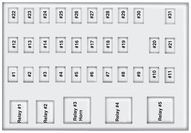
| № | A | Protected Circuits |
|---|---|---|
| 1 | 20A | Horn |
| 2 | 15A | Flasher relay |
| 3 | 20A | Power point |
| 4 | 10A | Data Link Connector (DLC), Engine diagnostic connector, Parking brake warning |
| 5 | 15A | Run relay |
| 6 | - | Not used |
| 7 | - | Not used |
| 8 | 5A | Radio, GEM |
| 9 | 5A | Power window relay |
| 10 | 15A | Heated mirrors |
| 11 | 5A | Wiper and washer systems |
| 12 | 10A | Transmission shift selector |
| 13 | 20A | Radio/SYNC, Power mirrors |
| 14 | 10A | Interior lamp relay |
| 15 | 10A | Interior lamp relay |
| 16 | 15A | High beams, Indicator |
| 17 | - | Not used |
| 18 | 5A | Dimmer switch, Interior lighting |
| 19 | 15A | Engine control (diesel engine only) |
| 20 | 5A | Starting system |
| 21 | 10A | DRL resistor |
| 22 | 15A | Air horn, Air suspension dump, Two-speed axle, Driver-controlled locking differential |
| 23 | 10A | Flasher relay |
| 24 | 15A | Hydraulic brakes relay, Fuel heater relay (diesel engine only), Air dryer |
| 25 | 10A | Blower motor relay coil |
| 26 | 10A | Right-hand low beam headlight |
| 27 | - | Not used |
| 28 | 10A | Left-hand low beam headlight |
| 29 | 10A | Cluster, GEM |
| 30 | 15A | Allison electronic transmission |
| 31 | 15A | Mirror fold relay |
| Relay 1 | - | Interior lamps |
| Relay 2 | - | Not used |
| Relay 3 | - | Horn |
| Relay 4 | - | Not used |
| Relay 5 | - | Not used |
Power Distribution Box
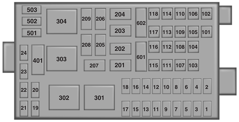
| № | A | Protected Circuits |
|---|---|---|
| 1 | 20A | Upfitter switches (AUX 2 and AUX 4)/Trailer 12V socket pin |
| 2 | 30A | Power seat (driver) |
| 3 | 30A | Power seat (passenger) |
| 4 | 15A | Windshield washer relay, Washer pump motor |
| 5 | 5A | Brake warning switch (hydraulic brake vehicles only) |
| 6 | 20A | Upfitter switches (AUX 1 and AUX 3) |
| 7 | 15A | Brake pressure switches, ABS event relay |
| 8 | 20A | DEF (Urea) line heaters (diesel engine only) |
| 9 | 20A | Ignition switch, Starter cutoff |
| 10 | 15A | Air tank moisture removal valve |
| 11 | 30A | Electric trailer brake |
| 12 | 20A | Passenger compartment fuse box 5 and 21 |
| 13 | 15A | Instrument cluster/Gateway module |
| 14 | 20A | Nitrogen oxide sensor (diesel engine only) |
| 15 | - | Not used |
| 16 | 5A | Bendix Air ABS |
| 17 | - | Not used |
| 18 | 10A | Fuel transfer pump |
| 19 | 15A | Powertrain control module power 1 (gasoline engine only) |
| 20 | 10A | Powertrain control module power 2 (gasoline engine only) |
| 21 | 20A | Powertrain control module power 3 (gasoline engine only) |
| 22 | 20A | Powertrain control module power 4 (gasoline engine only) |
| 23 | - | Not used |
| 24 | 10A | Powertrain control module keep-alive power (gasoline engine only) |
| 101 | 30A | Bendix Air ABS relay (Air brake vehicles only) |
| Hydraulic brakes module (hydraulic brake vehicles only) | ||
| 102 | 20A | Ignition switch |
| 103 | 20A | Ignition switch, Passenger compartment fuse box fuses 19, 29 and 30 |
| 104 | 20A | Power point |
| 105 | 20A | Power door lock switches |
| 106 | 30A | Main light switch, Multi-function switch |
| 107 | 50A | Passenger compartment fuse box fuses 1,2, 3, 4, 12, 13, 14 and 15 |
| 108 | 40A | Fuel heater (diesel engine only) |
| 20A | Fuel pump module (gasoline engine only) | |
| 109 | 40A | Power window |
| 110 | 30A | Windshield wiper |
| 111 | 30A | Body builder relay, Parking lamps |
| 112 | 40A | Blower motor |
| 113 | 30A | Heated seats, Air-Ride seat |
| 114 | 20A | Aftertreatment DCU |
| 115 | 20A | Ignition switch, Passenger compartment fuse box fuses 8, 9, 10 and 11 |
| 116 | 30A | Left/Right turn relays, Back up lamp relay |
| 117 | 20A | Stop lamps |
| 118 | 60A | Hydraulic brake vehicles (trailer tow package only) |
| 601 | 60A | Trailer socket |
| 602 | 60A | Air brake trailer tow fuse block |
| 30A | Hydraulic brakes pump motor 2 | |
| 201 | - | Windshield washer relay |
| 202 | - | Wiper high/low relay |
| 203 | - | Wiper run/park relay |
| 204 | - | Windshield wiper relay |
| 205 | - | Body builder relay, right turn |
| 206 | - | Body builder relay, left turn |
| 207 | - | ABS event relay (hydraulic brake vehicles only) |
| 208 | - | Body builder relay, back up lamps relay |
| 209 | - | Auxiliary stop lamp relay |
| 301 | - | Fuel heater/Fuel transfer pump relay (diesel engine only) |
| - | Fuel pump module (gasoline engine only) | |
| 302 | - | Body builder relay, parking lamps relay |
| 303 | - | Blower motor relay |
| 304 | - | DEF (Urea) line heaters relay (diesel engine only) |
| - | Powertrain control module power VPWR1 (gasoline engine only) | |
| 9925 | 30A | Hydraulic brakes pump motor 1 |
Relay Center
The relay center is located along the passenger side A-pillar on the right side of the footwell.

| № | Relay Description |
|---|---|
| R1 | Spring applied hydraulic release warning chime module or PCM power VPWR 2, 3 and 4 |
| R2 | A/C compressor clutch |
| R3 | Power Windows |
| R4 | Flasher (standard/LED) |
| R5 | Upfitter relay 1 |
| R6 | Upfitter relay 2 |
| R7 | Headlights |
| R8 | Spare |
| R9 | Upfitter relay 3 |
| R10 | Starter |
| R11 | DCU (diesel engine only) |
| R12 | Two-speed axle/Differential lock |
| R13 | Door lock |
| R14 | Air tank moisture valve |
| R15 | DRL #1 |
| R16 | Heated mirrors |
| R17 | Spare |
| R18 | Upfitter relay 4 |
| R19 | Shift interlock/EPRNDL display |
| R20 | Selective Catalyst Reduction (SCR) system (NOx) (diesel engine only) |
| R21 | Run |
| R22 | Door unlock |
| R23 | ABS warning indicator |
| R24 | DRL #2 |
| R25 | Park lights |
| R26 | Spare |
Trailer Tow Relays (If Equipped)
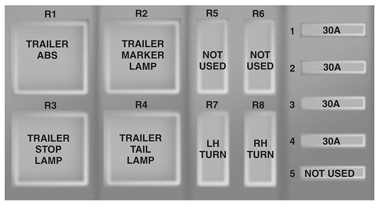
| № | A | Protected Circuits |
|---|---|---|
| 1 | 30A* | Trailer tow ABS feed (non electric trailer brake vehicles only) |
| 2 | 30A* | Trailer tow park/marker lamps |
| 3 | 30A* | Trailer tow stop lamps |
| 4 | 30A* | Trailer tow turn/stop lamps (combined) |
| Trailer tow turn lamps (separate) | ||
| 5 | - | Not used |
| R1 | - | Trailer tow ABS relay (non electric trailer brake vehicles only) |
| R2 | - | Trailer tow marker lamp relay |
| R3 | - | Trailer tow stop lamp relay |
| R4 | - | Trailer tow tail lamp relay |
| R5 | - | Not used |
| R6 | - | Not used |
| R7 | - | Trailer tow left turn lamp relay |
| R8 | - | Trailer tow right turn lamp relay |
| *Maxi fuse | ||
Inline fuses
Your vehicle may have several inline fuses located in/on the battery cables located in the battery box depending on application.
- All Allison transmission equipped vehicles have a 10 Amp fuse located in the clean power cables located in the battery box.
- All vehicles have a 30 Amp fused located in the clean power cables located in the battery box.
- All vehicles equipped with an Eaton transmission have a 30 Amp fuse located in the clean power cables located in the battery box.
- All Hydraulic brake equipped vehicles have a 40 Amp fuse located in the clean power cables located in the battery box and in addition another 30 Amp fuse located in a fuse holder just above the power distribution center located in the vehicles engine compartment.
2015
Passenger Compartment Fuse Panel

| № | A | Protected Circuits |
|---|---|---|
| 1 | 20A | Horn |
| 2 | 15A | Flasher relay |
| 3 | 20A | Power point |
| 4 | 10A | Data Link Connector (DLC), Engine diagnostic connector, Parking brake warning |
| 5 | 15A | Run relay |
| 6 | - | Not used |
| 7 | - | Not used |
| 8 | 5A | Radio, GEM |
| 9 | 5A | Power window relay |
| 10 | 15A | Heated mirrors |
| 11 | 5A | Wiper and washer systems |
| 12 | 10A | Transmission shift selector |
| 13 | 20A | Radio/SYNC, Power mirrors |
| 14 | 10A | Interior lamp relay |
| 15 | 10A | Interior lamp relay |
| 16 | 15A | High beams, Indicator |
| 17 | - | Not used |
| 18 | 5A | Dimmer switch, Interior lighting |
| 19 | 15A | Engine control (diesel engine only) |
| 20 | 5A | Starting system |
| 21 | 10A | DRL resistor |
| 22 | 15A | Air horn, Air suspension dump, Two-speed axle, Driver-controlled locking differential |
| 23 | 10A | Flasher relay |
| 24 | 15A | Hydraulic brakes relay, Fuel heater relay (diesel engine only), Air dryer |
| 25 | 10A | Blower motor relay coil |
| 26 | 10A | Right-hand low beam headlight |
| 27 | - | Not used |
| 28 | 10A | Left-hand low beam headlight |
| 29 | 10A | Cluster, GEM |
| 30 | 15A | Allison electronic transmission |
| 31 | 15A | Mirror fold relay |
| Relay 1 | - | Interior lamps |
| Relay 2 | - | Not used |
| Relay 3 | - | Horn |
| Relay 4 | - | Not used |
| Relay 5 | Not used |
Power Distribution Box

| № | A | Protected Circuits |
|---|---|---|
| 1 | 20A | Upfitter switches (AUX 2 and AUX 4)/Trailer 12V socket pin |
| 2 | 30A | Power seat (driver) |
| 3 | 30A | Power seat (passenger) |
| 4 | 15A | Windshield washer relay, Washer pump motor |
| 5 | 5A | Brake warning switch (hydraulic brake vehicles only) |
| 6 | 20A | Upfitter switches (AUX 1 and AUX 3) |
| 7 | 15A | Brake pressure switches, ABS event relay |
| 8 | 20A | DEF (Urea) line heaters (diesel engine only) |
| 9 | 20A | Ignition switch, Starter cutoff |
| 10 | 15A | Air tank moisture removal valve |
| 11 | 30A | Electric trailer brake |
| 12 | 20A | Passenger compartment fuse box 5 and 21 |
| 13 | 15A | Instrument cluster/Gateway module |
| 14 | 20A | Nitrogen oxide sensor (diesel engine only) |
| 15 | - | Not used |
| 16 | 5A | Bendix Air ABS |
| 17 | - | Not used |
| 18 | 10A | Fuel transfer pump |
| 19 | 15A | Powertrain control module power 1 (gasoline engine only) |
| 20 | 10A | Powertrain control module power 2 (gasoline engine only) |
| 21 | 20A | Powertrain control module power 3 (gasoline engine only) |
| 22 | 20A | Powertrain control module power 4 (gasoline engine only) |
| 23 | - | Not used |
| 24 | 10A | Powertrain control module keep-alive power (gasoline engine only) |
| 101 | 30A | Bendix Air ABS relay (Air brake vehicles only) |
| Hydraulic brakes module (hydraulic brake vehicles only) | ||
| 102 | 20A | Ignition switch |
| 103 | 20A | Ignition switch, Passenger compartment fuse box fuses 19, 29 and 30 |
| 104 | 20A | Power point |
| 105 | 20A | Power door lock switches |
| 106 | 30A | Main light switch, Multi-function switch |
| 107 | 50A | Passenger compartment fuse box fuses 1,2, 3, 4, 12, 13, 14 and 15 |
| 108 | 40A | Fuel heater (diesel engine only) |
| 20A | Fuel pump module (gasoline engine only) | |
| 109 | 40A | Power window |
| 110 | 30A | Windshield wiper |
| 111 | 30A | Body builder relay, Parking lamps |
| 112 | 40A | Blower motor |
| 113 | 30A | Heated seats, Air-Ride seat |
| 114 | - | Not used |
| 115 | 20A | Ignition switch, Passenger compartment fuse box fuses 8, 9, 10 and 11 |
| 116 | 30A | Left/Right turn relays, Back up lamp relay |
| 117 | 20A | Stop lamps |
| 118 | 60A | Hydraulic brake vehicles (trailer tow package only) |
| 601 | 60A | Trailer socket |
| 602 | 60A | Air brake trailer tow fuse block |
| 201 | - | Windshield washer relay |
| 202 | - | Wiper high/low relay |
| 203 | - | Wiper run/park relay |
| 204 | - | Windshield wiper relay |
| 205 | - | Body builder relay, right turn |
| 206 | - | Body builder relay, left turn |
| 207 | - | ABS event relay (hydraulic brake vehicles only) |
| 208 | - | Body builder relay, back up lamps relay |
| 209 | - | Auxiliary stop lamp relay |
| 301 | - | Fuel heater/Fuel transfer pump relay (diesel engine only) |
| - | Fuel pump module (gasoline engine only) | |
| 302 | - | Body builder relay, parking lamps relay |
| 303 | - | Blower motor relay |
| 304 | - | DEF (Urea) line heaters relay (diesel engine only) |
| - | Powertrain control module power VPWR1 (gasoline engine only) | |
| 9925 | 30A | Hydraulic brakes pump motor 1 |
Relay Center
The relay center is located along the passenger side A-pillar on the right side of the footwell.

| № | Relay Description |
|---|---|
| R1 | Spring applied hydraulic release warning chime module or PCM power VPWR 2, 3 and 4 |
| R2 | A/C compressor clutch |
| R3 | Power Windows |
| R4 | Flasher (standard/LED) |
| R5 | Upfitter relay 1 |
| R6 | Upfitter relay 2 |
| R7 | Headlights |
| R8 | Cummins starter lockout |
| R9 | Upfitter relay 3 |
| R10 | Starter |
| R11 | DCU (diesel engine only) |
| R12 | Two-speed axle/Differential lock |
| R13 | Door lock |
| R14 | Air tank moisture valve |
| R15 | DRL #1 |
| R16 | Heated mirrors |
| R17 | Spare |
| R18 | Upfitter relay 4 |
| R19 | Shift interlock/EPRNDL display |
| R20 | Selective Catalyst Reduction (SCR) system (NOx) (diesel engine only) |
| R21 | Run |
| R22 | Door unlock |
| R23 | ABS warning indicator |
| R24 | DRL #2 |
| R25 | Park lights |
| R26 | Spare |
Trailer Tow Relays (If Equipped)

| № | A | Protected Circuits |
|---|---|---|
| 1 | 30A* | Trailer tow ABS feed (non electric trailer brake vehicles only) |
| 2 | 30A* | Trailer tow park/marker lamps |
| 3 | 30A* | Trailer tow stop lamps |
| 4 | 30A* | Trailer tow turn/stop lamps (combined) |
| Trailer tow turn lamps (separate) | ||
| 5 | - | Not used |
| R1 | - | Trailer tow ABS relay (non electric trailer brake vehicles only) |
| R2 | - | Trailer tow marker lamp relay |
| R3 | - | Trailer tow stop lamp relay |
| R4 | - | Trailer tow tail lamp relay |
| R5 | - | Not used |
| R6 | - | Not used |
| R7 | - | Trailer tow left turn lamp relay |
| R8 | - | Trailer tow right turn lamp relay |
| *Maxi fuse | ||
Inline Fuses
Your vehicle may have several inline fuses located in, or on, the battery cables located in the battery box (depending on application).
- All vehicles equipped with an Allison transmission have a 10 amp fuse located in the clean power cables located in the battery box.
- All vehicles have a 30 amp fuse located in the clean power cables located in the battery box.
- All vehicles equipped with hydraulic brakes have a 40 amp fuse located in the clean power cables located in the battery box. In addition, another 30 amp fuse is located in a fuse holder just above the power distribution center located in the vehicle’s engine compartment.