Page Contents:
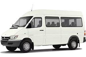
In this article, you will find information about the fuses of the Dodge Sprinter (models 2005 and 2006), including diagrams of the fuse boxes, a list of fuses and relays, their designation, and the location of the fuse blocks within the vehicle.
Checking and Replacing Fuses in Dodge Sprinter
Damaged fuses are recognizable from their burnt-out filament. Prior to exchanging a fuse, turn the key in the ignitioncolumn lock to the 0 position and switch off the consumer involved.
Caution!
When replacing a blown fuse, it is important to use only a fuse having the correct amperage rating. The use of a fuse with a rating other than indicated may result in a dangerous electrical system overload. If a properly rated fuse continues to blow, it indicates a problem in the circuit that must be corrected.
Location of Fuse Boxes
Standard Fuse and Relay Equipment:
Fuses and relays (standard equipment) are on the underside of the ignition column.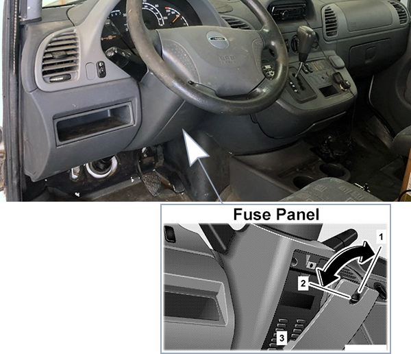
- Locked
- Unlocked
- Detent spring – engage when the cover is fitted
Optional Fuse and Relay Equipment:
The cover is located below the driver’s seat. Removing cover: Press both detent springs down and remove cover. Installing cover: Position cover at bottom and engage both detent springs.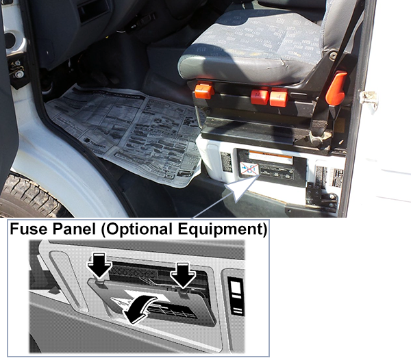
Fuse Box Diagrams
2005
Standard Equipment
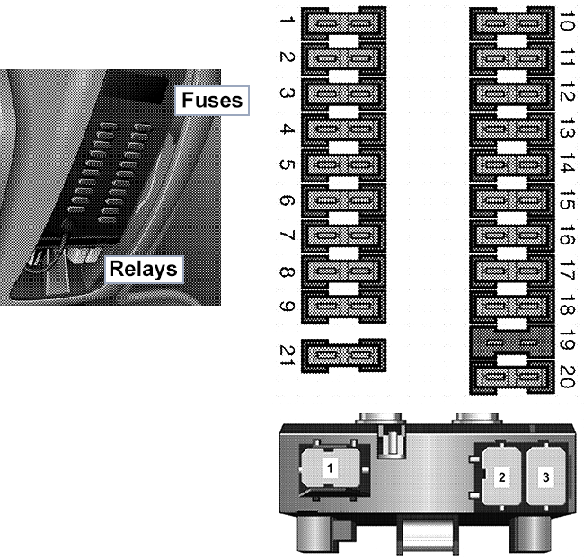
| № | A | Circuit |
|---|---|---|
| 1 | 10A | Parking lamp right, taillamp right |
| 2 | 10A | High beam head lamp, right |
| 3 | 10A | High beam head lamp, left, high beam indicator lamp |
| 4 | 10A | Backup lamp |
| 5 | 10A | Brake lamp |
| 6 | 20A | Windshield wiper motor |
| 7 | 15A | Horn, heated rear window, air recirculation switch, optional equipment relay (terminal 15) |
| 8 | 20A | Interior lighting, cigarette lighter, radio (terminal 30) |
| 9 | 15A | Clock, hazard warning lamps, parking lamps |
| 10 | 10A | Instrument lighting, license plate lamp daytime driving lamps |
| 11 | 10A | Side lamp, left; taillamp, left |
| 12 | 10A | Low beam headlamp, right |
| 13 | 10A | Low beam headlamp, left |
| 14 | 15A | Fog lamp |
| 15 | 10A | Radio (terminal 15) |
| 16 | 25A | Engine control unit |
| 17 | 15A | Engine control unit |
| 18 | 15A | Ignition (terminal 15) |
| 19 | 15A | Not in use |
| 20 | 15A | Heater controls (terminal 30) |
| 21 | 30A | Heater blower (terminal 30) |
| 1 | Windshield wiper motor (W) | |
| 2 | Diesel engine control unit (M) | |
| 3 | Turn signals (B) | |
Optional Equipment
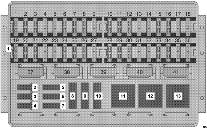
Note: The arrangement of the fuses (1) depends on the optional equipment installed on the vehicle. The assignments are shown on the inside of the cover of the fuse box.
| № | A | Circuit |
|---|---|---|
| 5 | 10A | Immobilizer |
| 6 | 7.5A | Anti-lock brake system (ABS) / Electronic Stability program (ESP) |
| 7 | 25A | Anti-lock brake system (ABS) / Electronic Stability program (ESP) - 2500 Type Vehicles |
| 8 | 40A | Not in use / Electronic Stability program (ESP) - 2500 Type Vehicles |
| 9 | 40A | Anti-lock brake system (ABS) |
| 10 | Not in use | |
| 11 | Not in use | |
| 12 | Starter relay | |
| 13 | Not in use | |
2006
Standard Equipment

| № | A | Circuit |
|---|---|---|
| 1 | 10A | Parking lamp right, taillamp right |
| 2 | 10A | High beam head lamp,right |
| 3 | 10A | High beam head lamp, left, high beam indicator lamp |
| 4 | 10A | Backup lamp |
| 5 | 10A | Brake lamp |
| 6 | 20A | Windshield wiper motor |
| 7 | 15A | Horn, heated rear window, air recirculation switch, optional equipment relay (terminal 15) |
| 8 | 20A | Interior lighting, cigarette lighter, radio (terminal 30) |
| 9 | 15A | Clock, hazard warning lamps, parking lamps |
| 10 | 10A | Instrument lighting, license plate lamp daytime driving lamps |
| 11 | 10A | Side lamp, left; taillamp, left |
| 12 | 10A | Low beam headlamp, right |
| 13 | 10A | Low beam headlamp, left |
| 14 | 15A | Fog lamp |
| 15 | 10A | Radio (terminal 15) |
| 16 | 25A | Engine control unit |
| 17 | 15A | Engine control unit |
| 18 | 15A | Ignition (terminal 15) |
| 19 | 15A | Not in use |
| 20 | 15A | Heater controls (terminal 30) |
| 21 | 30A | Heater blower (terminal 30) |
| 1 | Windshield wiper motor (W) | |
| 2 | Diesel engine control unit (M) | |
| 3 | Turn signals (B) | |
Optional Equipment

Note: The arrangement of the fuses (1) depends on the optional equipment installed on the vehicle. The assignments are shown on the inside of the cover of the fuse box.
| № | A | Circuit |
|---|---|---|
| 5 | 10A | Immobilizer |
| 6 | 7.5A | Anti-lock brake system (ABS) / Electronic Stability program (ESP) |
| 7 | 25A | Anti-lock brake system (ABS) / Electronic Stability program (ESP) - 2500 Type Vehicles |
| 8 | 40A | Not in use / Electronic Stability program (ESP) - 2500 Type Vehicles |
| 9 | 40A | Anti-lock brake system (ABS) |
| 10 | Not in use | |
| 11 | Not in use | |
| 12 | Starter relay | |
| 13 | Not in use | |