Page Contents:
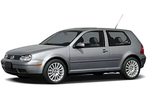
In this article, you will find information about the fuses of the Volkswagen Golf IV / Volkswagen Jetta / Volkswagen Bora (models 1998, 1999, 2000, 2001, 2002, 2003, 2004, and 2005), including diagrams of the fuse boxes, a list of fuses and relays, their designation, and the location of the fuse blocks within the vehicle.
Checking and Replacing Fuses in VW Golf IV & Jetta
Caution!
- Using the wrong fuse, using a blown fuse that has been repaired, and using metal objects in place of fuses to complete the electrical connection in the circuit can cause fires and serious personal injury. Never replace a fuse with one that has a higher amp rating. Replace a blown fuse only with a fuse of the same amperage (same color and same imprint) and same overall size. Never repair fuses. Never replace fuses with a metal strip, a paper clip, or a similar object.
- To avoid damaging the electrical system, turn off all lights and accessories and remove the ignition key before replacing a
Passenger Compartment Fuse Box
The central electric panel (fuse panel) is located behind an access panel on left edge of the Instrument panel. It contains both standard size fuses and mini-fuses. The use of mini-fuses allows protection of individual circuits.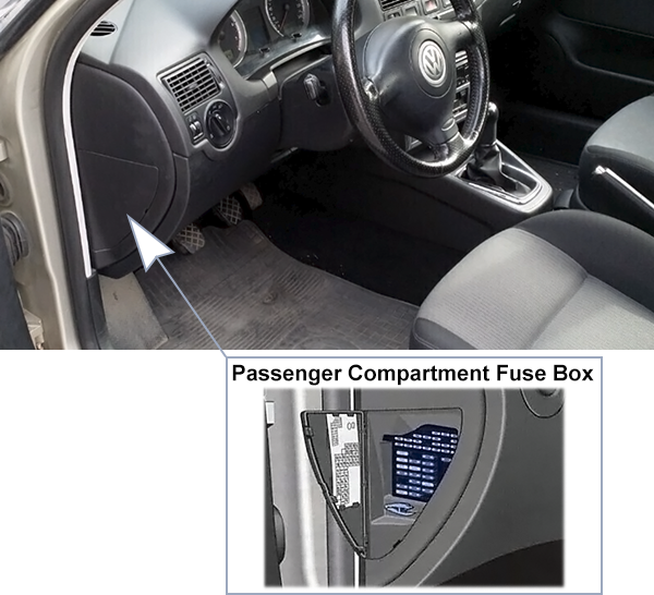
The power windows are also protected by a circuit breaker. If these fuses are overloaded (for example, if the windows are frozen shut), the circuit breaker will automatically switch off and then on again after a few seconds to help prevent the fuse from being blown.
Fuse Box Diagram
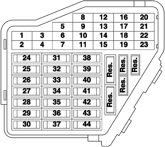
| № | A | Description |
|---|---|---|
| 1 | 10A | Heated washer nozzles, glove compartment light, memory seat |
| 2 | 10A | Turn signal system |
| 3 | 5A | Fog light relay, inst. panel dimmer switch |
| 4 | 5A | License plate light |
| 5 | 7.5A | Comfort system, cruise control, Climatronic, A/C, heated seat control modules, day/night dimming mirror, control module and control unit for multi-function steering wheel |
| 6 | 5A | Central locking system |
| 7 | 10A | Back-up iights, speedometer vehicle speed sensor |
| 8 | - | - |
| 9 | 5A | Anti-lock brakes (ABS) |
| 10 | 10A | ECM, gasoline engine |
| 5A | ECM, diesel engine (m.y. 2000 >) | |
| 11 | 5A | Instrument cluster, shift lock solenoid |
| 12 | 7.5A | B+ (battery positive voltage) for Data Link Connector (DLC) |
| 13 | 10A | Brake lights |
| 14 | 10A | Interior lights, central locking system |
| 15 | 5A | Instrument cluster, automatic transmission control module (TCM) |
| 16 | 10A | A/C clutch, after-run coolant pump |
| 17 | - | - |
| 18 | 10A | High beam right |
| 19 | 10A | High beam left |
| 20 | 15A | Low beam right |
| 21 | 15A | Low beam left |
| 22 | 5A | Parking and side marker lights, right |
| 23 | 5A | Parking and side marker lights, ieft |
| 24 | 20A | Front wiper motor, washer pump |
| 25 | 25A | Fresh air blower, Climatronic, A/C |
| 26 | 25A | Rear window defogger |
| 27 | 15A | Rear wiper motor |
| 28 | 15A | Fuel pump, gasoline |
| 29 | 15A | Engine control module (ECM), gasoline |
| 10A | Engine control module (ECM), diesel | |
| 30 | 20A | Sunroof control module |
| 31 | 20A | Automatic transmission control module |
| 32 | 10A | Fuel Injectors (gasoline) |
| 15A | ECM (diesel) | |
| 33 | 20A | Headlight washer system |
| 34 | 10A | Engine control elements |
| 35 | 30A | 12V power outlet (in luggage comp.) |
| 36 | 15A | Fog lights |
| 37 | 10A | Radio terminal 86S, instrument cluster |
| 38 | 15A | Central locking system (with power windows) luggage compartment light, remote fuel tank door, rear lid unlock |
| 39 | 15A | Emergency flashers |
| 40 | 20A | Dual tone horn |
| 41 | 15A | Cigarette lighter |
| 42 | 25A | Radio system |
| 43 | 10A | Engine control elements |
| 44 | 15A | Heated seats |
Relay Panel
The relay panel is located under the left side of the instrument panel.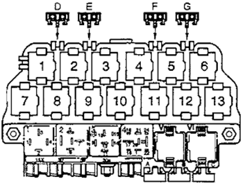
| № | A | Description |
|---|---|---|
| 1 | Dual horn relay | |
| 2 | Load reduction relay | |
| 3 | - | |
| 4 | Fuel pump relay | |
| V, VI | Wiper/Washer intermittent relay | |
| A | - | Power (Memory) seat circuit breaker |
| B | - | - |
| C | - | Power windows, central locking, heated power mirrors |
| 1 | - | |
| 2 | Rear lid remote unlock motor relay (up to 01.1999) | |
| 3 | Anti-thett starter lock relay (clutch pedal switch) | |
| 4 | Fog light relay | |
| 5 | Multi-function steering wheel relay (as applicable) | |
| 6 | Multi-function steering wheel relay (as applicable) | |
| 7 | Daytime running lights (from April 1999) | |
| 8 | Daytime running lights (through March 1999) | |
| 9 | - | |
| 10 | Glow plug relay | |
| 11 | Park/Neutral position relay | |
| 12 | Power supply (terminal 30b, B+) relay | |
| 13 | - | |
| D | - | - |
| E | - | - |
| F | 15A | Central locking, anti-theft warning |
| G | 15A | Central locking, anti-theft warning |
Engine Compartment Fuse Box
There is also a main fuse box located on top of the battery in the engine compartment. It contains special fuses for high cur-rent applications and prevents the main wiring harness in the event of a short circuit. To access these fuses, squeeze tabs of plastic fuse cover and pull upward.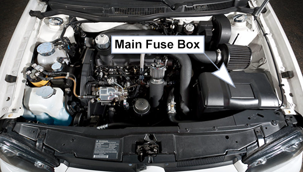
Fuse Box Diagram
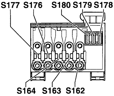
| № | A | Function |
|---|---|---|
| S162 | 50A | Secondary air injection relay or coolant pre-heating relays |
| S163 | 50A | Fuel pump relay or glow plug relay |
| S164 | 40A | Coolant fan and control module |
| S176 | 110A | Interior relay panel |
| S177 | 110A | Generator (90 Amp) |
| 150A | Generator (120 Amp) | |
| S178 | 30A | ABS-hydraulic pump |
| S179 | 30A | ABS |
| S180 | 30A | Coolant fan |